Fixposition Vision-RTK 2 GPS
This tutorial will guide you through the process of connecting Fixposition Vision-RTK 2 to Leo Rover.
Fixposition Vision RTK2 is a great GPS module capable of achieving up-to a centimeter-level accuracy. This system leverages Real-TimeKinematic (RTK) and vision-based positioning technology to provide precise localization even in challenging environments. With its compact design Vision-RTK 2 empowers Leo Rover users to navigate with unparalleled accuracy, unlocking new possibilities for research, exploration, and industrial applications.
What to expect?
Your rover will be able to gather accurate GPS data and publish it on these ROS topics, enabling you to use it for navigation and other purposes in your projects.
Prerequisites
Referenced products
Hardware integration
Mounting
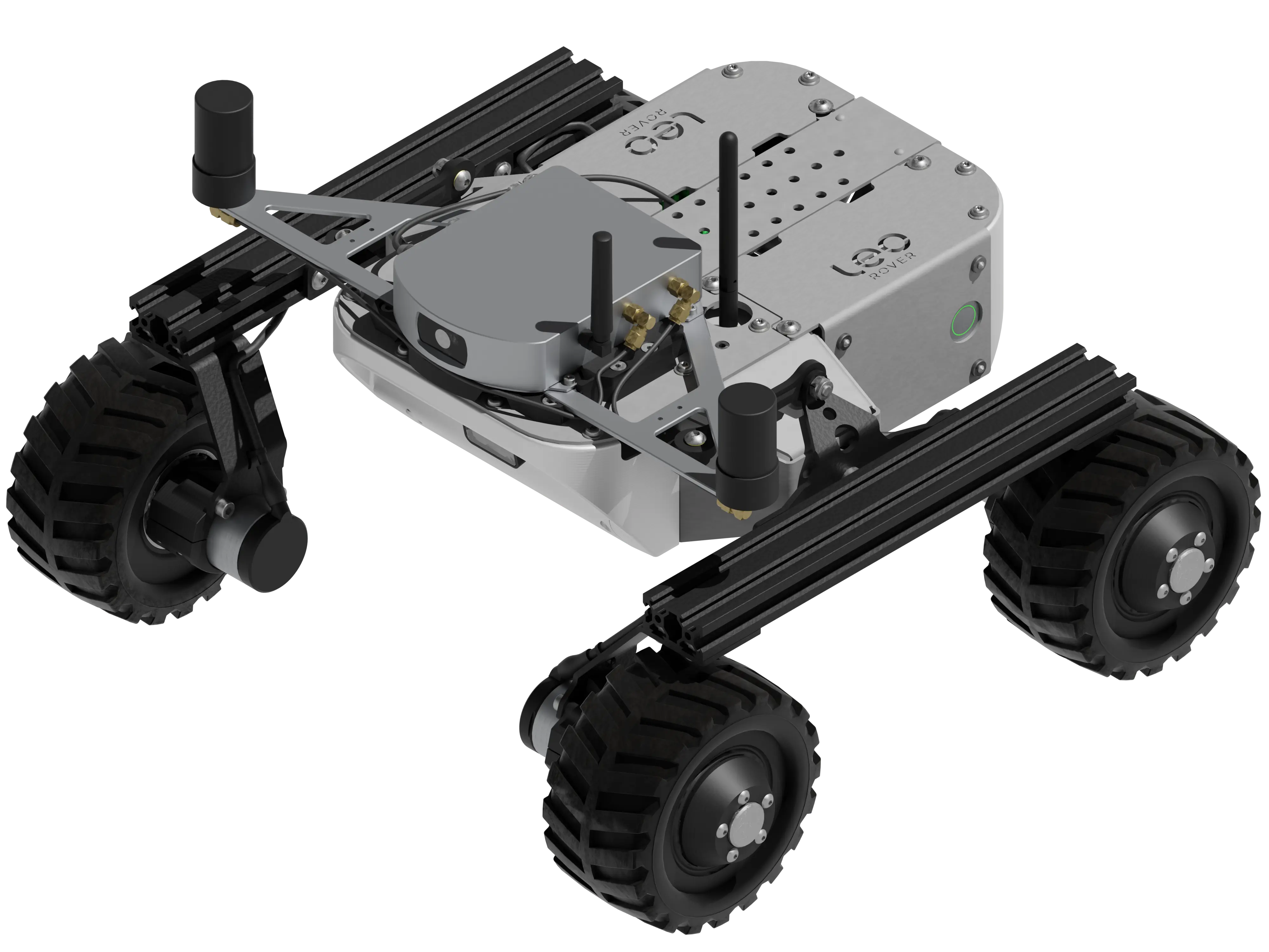
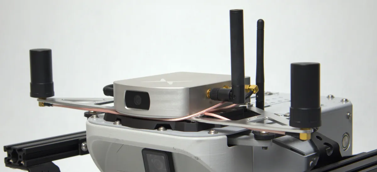
The module needs to be attached to the rover in a spot that provides an uninterrupted view of the terrain. An adapter plate (eg. the one we provide here) might be helpful to mount the module on the top of the rover.
The accuracy of the system depends on how far apart the GNSS antennas are spaced. Since Leo Rover is rather small it might be hard to place them more than 30cm apart. The system provides a satisfactory accuracy with setup like this, but it's not advised to go any closer. If your project allows it, try to position the antennas even further apart. It's also a good choice to move the GNSS antennas away from any parts of the rover that might be a source of electromagnetic interferences (e.g. motors).
Wiring
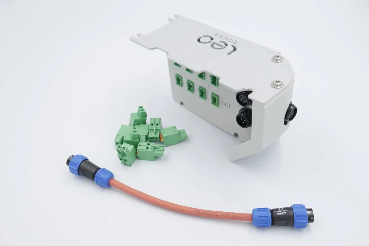
The only wire needed for the module to work is a power cable. An external power distribution module like our Powerbox might come in handy in this case.
When using Powerbox, you can connect the Vision RTK-2 power cable to one of the BAT ports.
Software integration
Before starting the software integration, please make sure that the sensor is properly configured. To do that you can complete the quick start guide and optionally follow the 4th and 5th chapters of the integration manual.
Few key points that can be helpful during the configuration process:
- Make sure that the sensor's firmware is at least version 2.102.2 or newer. You
can check the firmware version in the
system -> infotab of the web UI, under thesoftwarefield. If you have an older version, please update it following the instructions in the documentation. - Make sure to remember the sensor's IP address after connecting it to the rover network. You will need it later to configure the ROS driver.
- Make sure to enable the data flow from the sensor on
TCP0port in the web UI as this is the port used to communicate with the rover. I/O configuration options can be found in the I/O section of the documentation. Recommended minimal options to enable are:- FP_A-ODOMETRY
- FP_A-LLH
- NOV_B-BESTGNSSPOS_GNSS1
- NOV_B-BESTGNSSPOS_GNSS2
- FP_A-RAWIMU
- FP_A-CORRIMU
- FP_A-TF_POIVRTK
- FP_A-TF_VRTKCAM
- For more information refer to the official documentation.
Installing the driver
Having configured the sensor, you can now proceed with installing the fixposition driver.
For this task you need to install the fixposition ROS driver into a ROS workspace, therefore log in using ssh to the rover, and create a ROS workspace if you don't have one already:
mkdir -p ~/ros_ws/src
Then ensure that your rover has access to the internet and download the GitHub repository with the driver:
cd ~/ros_ws/src
git clone https://github.com/fixposition/fixposition_driver --recurse-submodules
Run the script from the driver repository to pre-configure the driver for installation:
cd fixposition_driver
./setup_ros_ws.sh
Now you can install all dependencies:
sudo apt update
sudo apt install git libyaml-cpp-dev libboost-all-dev zlib1g-dev libeigen3-dev linux-libc-dev nlohmann-json3-dev
cd ~/ros_ws
rosdep update
rosdep install --from-paths src -iry
Finally, you can build the workspace:
colcon build --symlink-install --cmake-args -DBUILD_TESTING=OFF
Driver configuration
Once the packages are installed, the driver needs to be configured to work
properly. To edit the configuration files, you can use nano or your preferred
text editor:
nano src/fixposition_driver/fixposition_driver_ros2/launch/config.yaml
Once you have the file open, change the stream parameter to include the
sensor's IP address in the rover network. It should look like this:
stream: tcpcli://<your sensor's IP>:21000
To avoid creation of numerous ROS topics, you can comment out (using #) the
unnecessary data streams in the messages field.
If you want the best performance make sure that the messages field corresponds
to the data streams enabled in the sensor's web UI.
Optionally to enable the driver to use the odometry data from the robot, you can
modify the converter parameters in the same file:
converter:
  enabled: true
  topic_type: 'Odometry' # Supported types: nav_msgs/{Twist, TwistWithCov, Odometry}
  input_topic: '/merged_odom' # Input topic name
  scale_factor: 1000.0 # To convert from the original unit of measurement to mm/s (note: this must be a float!)
  use_x: true # Transmit the x axis of the input velocity
  use_y: true # Transmit the y axis of the input velocity
  use_z: false # Transmit the z axis of the input velocity
If your robot has a namespace different than the default /, you need to
provide the input_topic param with the namespace. Make sure that the provided
topic name is in the global namespace - starting with /, e.g.
/namespace/merged_odom.
Adding the driver to autostart
The last part of the setup is to add the driver to autostart and make sure that
the frames published by the driver are connected to Leo Rover's tf tree.
Enter the setup.bash file of the Rover:
nano /etc/ros/setup.bash
Edit this file to source the ROS workspace where the driver is installed. Remember to comment out the default ROS setup line and source the custom workspace.
#source /opt/ros/jazzy/setup.bash
source ~/ros_ws/install/setup.bash
Now you can edit the launch file that is launched at the robot's startup to include the fixposition driver launch file and the static transform publisher that will connect the frames published by the driver to the robot:
nano /etc/ros/robot.launch.xml
And add these lines somewhere in between the launch tag:
<include file="$(find-pkg-share fixposition_driver_ros2)/launch/node.launch"/>
<node pkg="tf2_ros" exec="static_transform_publisher" name="fixposition_broadcaster"
      args="0 0 0 0 0 0 base_link FP_POI" />
Replace the args in the static transform publisher with the correct values for
your setup. The example above assumes that the base_link frame is in the same
position as the FP_POI frame.
To launch the driver, you can reboot the robot or restart the ROS nodes:
ros-nodes-restart
To view the ROS nodes logs for debugging purposes, you can use the following command:
ros-nodes-logs -f
Now you should have the driver up and running, and be able to see the data from the sensor in ROS, provided that the sensor has been properly configured and the correct data flow has been enabled in the sensor's web UI.
What's next?
Fixposition Vision-RTK 2 can be used in projects involving autonomous navigation. You might be interested in a tutorial about it.
You can also deploy long-duration mapping runs to capture centimeter-accurate site models or use the data from the sensor to improve the stability of your SLAM system.